Customize Waveform
You can customize the waveform and the customized waveform bank will be automatically stored on the computer so that it can be selected and used in the Sequencer view and Avionics view.
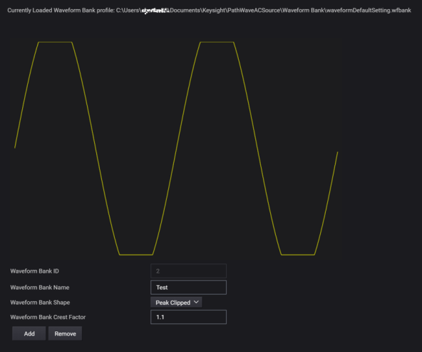
Add or Remove Waveform Bank
Click Add. Customize the waveform using the following settings.
To remove a waveform bank, select the waveform bank, click Remove.
Waveform Bank ID
A numeric index that automatically assigned to a Waveform Bank (from 1 to 256).
Waveform Bank Name
Enter the desired waveform bank name.
Waveform Bank Shape
Waveform bank location zero (0) contains a reference sine wave with a positive peak of 32767 points, a negative peak of 32767, with a cycle of 4096 points. The phase resolution is 0.01 degrees. Waveform bank location zero cannot be overwritten. In the factory default condition, all waveform bank locations contain this reference sine wave.
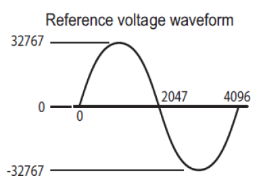
Select the waveform bank shape.
- Sine – The default waveform.
- Peak Clipped – The peak portion of waveforms is clipped by the specified crest factor value. The sine waveform is adjusted so that the specified rms value and the rms value of the waveform that is actually output are the same. For a sine wave, the crest factor is 1.41. In the voltage waveforms of commercial power lines, the peaks are clipped, so the crest factor is between 1.2 and 1.4.
- Flat Curve – This is a waveform defined in IEC61000-4-13. The peak of the waveform is clipped by the specified clip factor. The waveform peak is defined to be 1. The specified rms value and the rms value of the waveform that is actually output are not the same.
Waveform Bank Crest Factor
This setting is only available when Peak Clipped waveform bank shape is selected.
Set the waveform bank crest factor value (0.10 to 1.40).
Waveform Bank Clip Factor
This setting is only available when Flat Curve waveform bank shape is selected.
Set the waveform bank clip factor value (0.4 to 1.0).